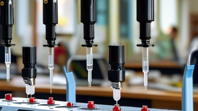
What Is a Liquid Handling System and How Does It Work?

A liquid handling system moves, measures, and dispenses liquids with controlled accuracy. It may serve a research laboratory, clinical facility, or quality control department. Some systems use electronic pipettes, while others combine robotic arms, pumps, valves, and disposable tips. The design depends on volume range, liquid properties, throughput, and contamination risk.

At its core, the system draws liquid from a source container into a pipette channel or probe. Sensors and software help control aspiration speed, dispensing volume, and movement. The system then transfers the liquid into wells, tubes, or other vessels. A technician usually defines the method through a software interface. Calibration remains essential. Even advanced equipment can produce unreliable results when tips leak, vessels are misaligned, or liquid viscosity changes.

In practical use, operators inspect the deck, confirm labware positions, and check the selected method before starting a run. Small details matter. A few droplets can affect an assay. Cleaning and maintenance also support repeatable performance and protect samples from carryover. However, automation is not a complete substitute for judgment. Unexpected foam, bubbles, evaporation, or unusual samples may require human review. That limitation deserves attention.

This guide explains how a liquid handling system works, where its accuracy comes from, and which factors influence daily performance. It also considers common mistakes, practical safeguards, and situations where manual handling may remain the better choice.
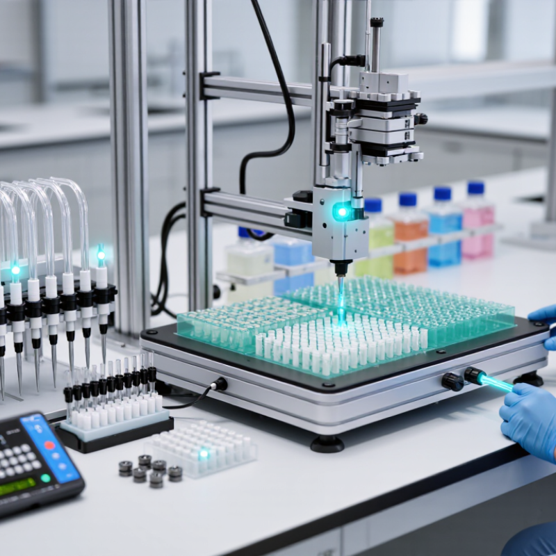
What Is a Liquid Handling System and How Does It Work?

Core Components of a Liquid Handling System

What Is a Liquid Handling System and How Does It Work?

Core Components of a Liquid Handling System

A liquid handling system transfers, measures, mixes, and dispenses fluids in laboratory workflows. Its performance depends on several connected components. The deck holds microplates, tubes, reservoirs, and disposable tips. Pipetting channels use pistons, pumps, or air displacement to move precise volumes. Valves control fluid paths, while robotic axes position each channel above the target vessel.

Sensors provide another layer of control. They can detect liquid levels, clogged tips, plate presence, and unexpected movement. Software converts a written protocol into timed commands. It also records volumes, positions, and error messages. According to Grand View Research’s 2024 market analysis, the global liquid handling systems market was valued at more than 4 billion dollars in 2023. That growth reflects demand for higher throughput and better traceability.

Accuracy does not come from automation alone. Tip geometry, liquid viscosity, temperature, and surface tension can change results. A calibration study by the National Institute of Standards and Technology has shown that measurement uncertainty must be evaluated across the complete workflow, not only at the pipette. Small errors accumulate. A clean-looking deck can still produce unreliable data when liquid-level detection is poorly tuned. That is the uncomfortable part.

Regular calibration, preventive maintenance, and control samples remain essential. Operators should review unusual readings instead of trusting software blindly. Even advanced systems need human judgment.

How Liquid Handling Systems Control Fluid Movement

A liquid handling system moves measured fluid between containers with controlled speed and volume. It combines pumps, valves, tubing, sensors, and disposable or reusable liquid-contact parts. The controller coordinates each movement through programmed settings. Aspiration creates controlled negative pressure, pulling liquid into a tip or probe. Dispensing reverses the pressure and releases fluid into a receiving vessel. Small adjustments matter. A fraction of a microliter can affect an analytical result.

Fluid movement depends on viscosity, temperature, surface tension, and liquid level. Sensors can detect whether a tip touches liquid or whether an obstruction interrupts flow. Air gaps may separate samples and reduce cross-contamination between transfers. Rinsing cycles clean internal pathways, while pressure monitoring helps identify leaks or blocked tubing. In practice, operators should match the transfer method to the liquid. Thick solutions need slower aspiration, while volatile liquids may require gentler pressure changes.

Reliable performance requires calibration and routine verification. A gravimetric check, using a calibrated balance, can reveal volume errors that software alone cannot detect. Operators should also inspect seals, tubing, and tips before critical runs. No system is perfect. Evaporation, droplets left on vessel walls, and inconsistent technique can still influence results. I have found that simple visual checks often expose problems early, although they cannot replace documented testing. Controls should be reviewed whenever the liquid, container, or operating temperature changes.

What Is a Liquid Handling System and How Does It Work? - How Liquid Handling Systems Control Fluid Movement
The performance ranges shown are representative engineering ranges. Actual capacity, accuracy, and flow rate depend on the instrument design, fluid properties, tubing, vessel geometry, and operating conditions.
System Type How It Controls Fluid Movement Typical Working Range Primary Control Variables Suitable Fluids and Applications Main Advantages and Limitations
Air-Displacement Pipetting A piston changes air pressure above the liquid. The pressure difference draws liquid into a disposable tip and then expels it. Approximately 0.1 µL–10 mL
Best suited to low-volume liquid transfer.
Piston stroke, aspiration speed, dispensing speed, air gap, tip immersion depth, and pause time. Aqueous buffers, diluted reagents, biological samples, and routine laboratory transfers. Fast Low contact
Sensitive to temperature, evaporation, air compression, and liquid viscosity.
Positive-Displacement Pipetting A piston directly contacts the liquid or uses a piston-like disposable tip, so liquid movement is determined by the mechanical displacement of the piston. Approximately 0.5 µL–10 mL
Commonly used for viscous or volatile liquids.
Piston stroke, piston speed, aspiration rate, dispensing rate, and tip geometry. High-viscosity fluids, volatile solvents, foaming liquids, oils, glycerol solutions, and samples affected by vapor pressure. Good liquid compatibility Stable dosing
Disposable piston tips can increase operating cost and waste.
Syringe Pump A motor drives a plunger through a syringe. The programmed displacement and movement speed determine the delivered volume and flow rate. About 1 µL–1 L per syringe
Flow rates commonly range from microliters to hundreds of milliliters per minute, depending on syringe size.
Plunger displacement, motor step size, syringe diameter, flow rate, acceleration, and valve timing. Precision reagent dosing, chromatography, analytical instruments, microfluidics, and continuous low-flow delivery. High precision Programmable flow
Limited by syringe capacity; refilling may interrupt continuous operation.
Peristaltic Pump Rotating rollers compress flexible tubing in sequence, creating a moving occlusion that pushes liquid forward without direct pump-to-fluid contact. Approximately 0.1–1,000 mL/min
The usable range depends strongly on tubing size and roller speed.
Roller speed, tubing internal diameter, tubing elasticity, number of rollers, and operating time. Nutrient media, water-based solutions, cell-processing fluids, and liquids requiring isolation from the pump mechanism. Self-priming Low contamination risk
Tubing fatigue can change flow rate and may generate pulsation.
Diaphragm Pump A flexible diaphragm repeatedly moves to create suction and discharge strokes. Check valves direct the fluid through the pump chamber. Approximately 1–500 mL/min
Some configurations support higher flow rates.
Diaphragm frequency, stroke length, valve response, inlet pressure, outlet pressure, and fluid resistance. Corrosive reagents, filtration systems, gas-liquid handling, and fluids that must remain separated from the drive mechanism. Chemically adaptable Good isolation
Flow can be pulsating, and valve performance depends on particle size and viscosity.
Solenoid Valve Dosing An electrically actuated valve opens or closes a fluid pathway. The transferred amount is controlled by opening time, pressure, and orifice size. Microliter to milliliter doses
Flow is application-dependent rather than fixed.
Valve open time, inlet pressure, orifice diameter, fluid viscosity, and valve response time. Reagent switching, wash cycles, discrete dispensing, fluid routing, and automated sampling. Rapid switching Compact
Timing alone may not provide accurate volume control when pressure or viscosity changes.
Pressure-Driven Liquid Handling Controlled air or gas pressure pushes liquid from a sealed reservoir through tubing, valves, and a dispensing outlet. Typically 1 µL–100 mL per dispense
Flow depends on pressure, resistance, and liquid properties.
Applied pressure, pressure ramp, dispense time, tubing resistance, liquid level, and outlet diameter. Multiwell dispensing, reagent distribution, sterile fluid transfer, and systems requiring sealed reservoirs. Low mechanical contact Easy parallelization
Liquid level and compressible air volume can affect repeatability.
Gravimetric Liquid Handling A load cell measures the mass of a vessel while a pump or valve adds or removes liquid. Volume is calculated from mass and liquid density. From small laboratory doses to bulk filling
Practical resolution depends on the balance and vessel size.
Measured mass, liquid density, pump speed, cutoff timing, vibration, and evaporation rate. Calibration, formulation, filling verification, standards preparation, and liquids with known density. Direct measurement Auditable results
Sensitive to vibration, splashing, air currents, and density changes caused by temperature.
Robotic Liquid Handling Platform Programmable motors position probes or vessels while pumps, pipettes, valves, and sensors coordinate aspiration, transfer, dispensing, and mixing. Sub-microliter to milliliter transfers
Capacity depends on the installed dispensing modules.
Position, volume, aspiration and dispense speed, liquid level detection, tip height, mixing cycles, and deck layout. High-throughput screening, sample preparation, diagnostic workflows, analytical testing, and repeatable laboratory protocols. High throughput Protocol automation
Requires method validation, calibration, contamination control, and correct liquid-class settings.

The Step-by-Step Process of Automated Liquid Transfer

A liquid handling system automates the controlled movement of liquids between tubes, plates, and reservoirs. Its work begins with a programmed method. The operator defines volumes, destinations, mixing cycles, and tip changes. The system then checks the deck layout and identifies each labware position.

The transfer starts when a pipette channel lowers into the source liquid. It aspirates a measured volume, often using an air cushion or positive displacement. The tip rises carefully. Sudden movement can create droplets or foam. The system travels to the receiving well and dispenses the liquid at a selected speed. It may pause, touch the wall, or mix repeatedly. Then, the used tip is ejected or washed, depending on the workflow. Small details matter.

Sensors and software monitor liquid levels, movement, and possible obstructions. Yet automation is not infallible. A bubble, poorly seated plate, or incorrect liquid height can change the result. Human review remains necessary, especially during method setup and validation. ISO 8655-2:2022 provides requirements for piston-operated volumetric instruments, including accuracy and precision testing. These checks help confirm that programmed volume matches delivered volume. Grand View Research estimated the laboratory automation market at about USD 5.3 billion in 2023, reflecting growing demand for repeatable workflows. Still, speed alone is not quality. A faster transfer can spread contamination if tip changes and surface contact are poorly controlled.

Common Liquid Handling System Configurations and Applications

A liquid handling system moves measured volumes between containers with controlled speed, position, and pressure. It may use air displacement, positive displacement, peristaltic pumps, or precision syringes. A programmable controller coordinates tips, valves, pumps, and robotic movement. Sensors can check liquid level, tip presence, and aspiration depth. Small errors matter.

Common configurations include single-channel, multichannel, and automated workstations. Single-channel systems suit flexible, low-volume tasks and unusual plate layouts. Multichannel systems transfer liquid across several wells at once, improving speed during microplate assays. Automated workstations combine pipetting, plate movement, mixing, heating, cooling, and barcode tracking. Modular systems are useful when laboratories expect changing workflows. However, extra modules also create more maintenance points.

These systems support sample preparation, serial dilution, reagent dispensing, nucleic acid workflows, cell-based assays, and analytical testing. A gentle aspiration setting can protect fragile cells, while controlled dispensing helps reduce bubbles in sensitive reactions. Viscous liquids often need slower movement and wider tips. Volatile liquids may require sealed containers and adjusted air gaps. In daily operation, calibration, leak checks, and scheduled cleaning remain essential. I have found that software cannot correct poor plate design or inconsistent source containers. The setup must be tested with real liquids, not water alone. It is not magic. Temperature, viscosity, foaming, and operator technique can still change results.

Key Factors Affecting Accuracy and Performance

A liquid handling system moves measured volumes between containers using pumps, valves, probes, and control software. Its performance depends on more than the instrument itself. Accuracy means reaching the intended volume, while precision means producing consistent results repeatedly. Both matter in routine laboratory work.

Temperature is a practical concern. A cold, viscous solution may move more slowly than water and leave residue inside a tip. Air bubbles can also reduce delivered volume. Even a small bubble matters. Operators should match aspiration speed to liquid properties and inspect tips before critical transfers. Correct calibration is essential, but calibration alone cannot repair poor technique or unsuitable settings.

Tip fit, container shape, liquid level, and evaporation also affect results. Narrow wells may cause the probe to touch a wall, while shallow liquids can increase aspiration errors. Regular gravimetric checks, repeated measurements, and clear maintenance records help reveal drift. In practice, cleaning schedules are sometimes treated as optional. That is a mistake. Yet no procedure is perfect; unusual samples may still behave unpredictably. Teams should review failed runs, question their assumptions, and adjust methods based on measured evidence rather than convenience.

What Is a Liquid Handling System and How Does It Work?

Reference Error Limits for Piston Pipetting at Different Volumes

Liquid handling systems aspirate and dispense liquids using pistons, pumps, valves, tubing, or robotic movement. The chart compares representative systematic and random error reference values for commonly used piston-pipette volumes. Accuracy is affected by calibration, liquid viscosity, temperature, tip sealing, aspiration speed, dispensing technique, and air bubbles. Smaller volumes generally require tighter technique and environmental control because small absolute errors become larger percentage errors.

Values are shown in microlitres (µL) and represent commonly used non-brand reference points for verification. Actual acceptance limits depend on pipette type, operating range, liquid properties, and the applicable laboratory standard.